Hybrid project
-
- Heavy Smoker
- Posts: 476
- Joined: Fri Jun 26, 2009 12:09 am
- Location: Kingdom of the Netherlands
Re: Hybrid project
With the LH spacer's width reduced to the required 10 mm I can now confirm the width of the RH spacer to be 6.3 mm and can get it made. From left to right: LH spacer, sprocket carrier bearing and spacer, LH wheel bearing, wheel bearing spacer, RH wheel bearing, spacer, vj22 RGV caliper carrier, and gap to be filled by the to be made spacer.
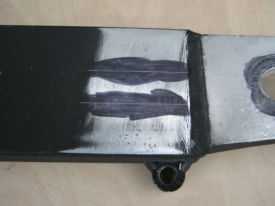
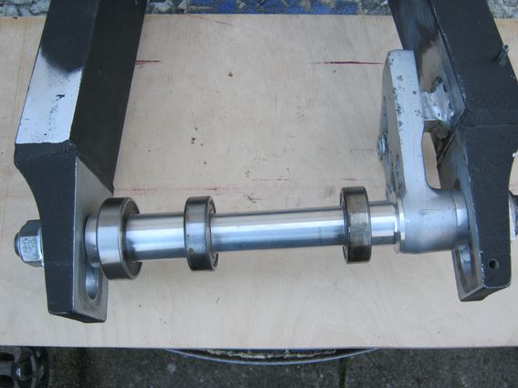
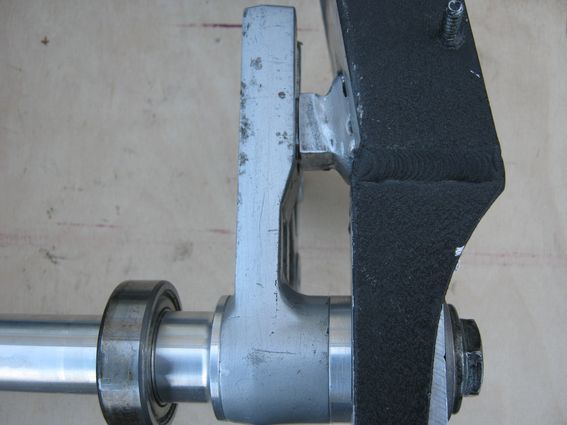
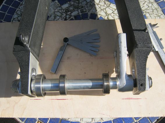
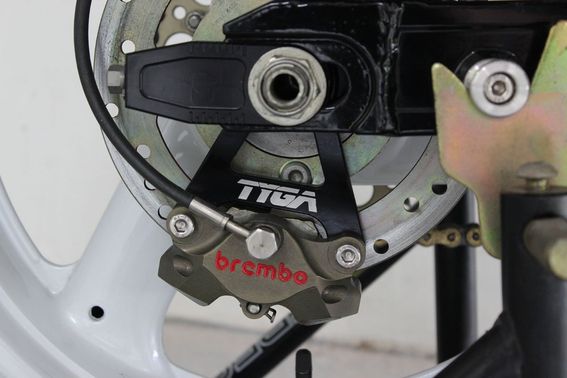
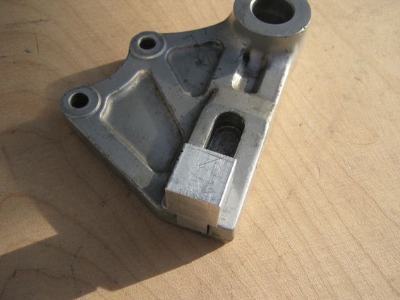
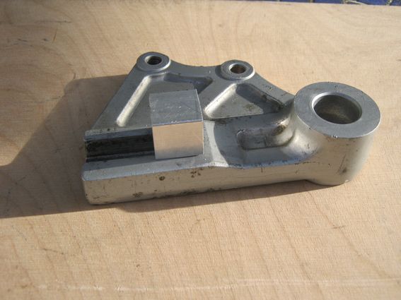
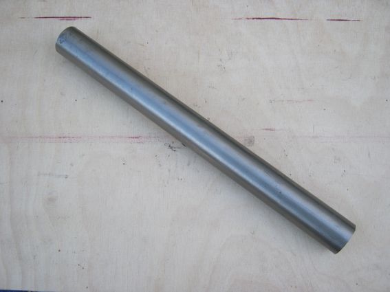
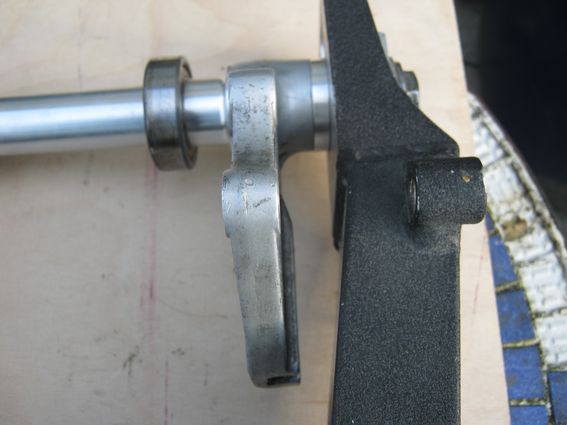
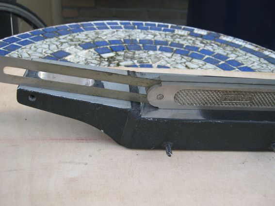
Note that this setup is for a vj22 RGV rear wheel, RGV 20 mm axle and vj22 RGV style caliper carrier. The dimensions quoted won't be correct for other parts.
"Mine is a long and sad tale", said the mouse.
"Indeed it is", said Alice, looking at the mouse's tail.
-
- Heavy Smoker
- Posts: 476
- Joined: Fri Jun 26, 2009 12:09 am
- Location: Kingdom of the Netherlands
Re: Hybrid project
The Suzuki vj22 RGV rear caliper carrier is prevented from rotating by a tongue and groove system: a tongue milled into the carrier....
..... which mates with a lug welded to the RH inside of the RGV swingarm (the swingarms in the pics aren't mine):
The lug is 12 mm thick nominally and the groove 13 mm wide giving a clearance of 1 mm (rattle clearance) which seems excessive but was probaby done so that positioning of the lug during manufacture wasn't too critical. Length of the lug is 20 mm (my thanks to SP_BOTT for the dimensions) so I obtained a length of 20 x 30 mm aluminium bar and cut off a 20 mm long section. The photo shows the tongue rough cut.
Next, my "favourite" pastime, filing the tongue to the correct size and shape..........
"Mine is a long and sad tale", said the mouse.
"Indeed it is", said Alice, looking at the mouse's tail.
-
- Heavy Smoker
- Posts: 476
- Joined: Fri Jun 26, 2009 12:09 am
- Location: Kingdom of the Netherlands
Re: Hybrid project
I haven't definitely decided yet which setup I will be using for the rear caliper assembly, but it will be either the GB Moto setup for the vj22 RGV:
..... or the Tyga rear caliper bracket for vj22 RGV:
...... with Brembo caliper:
Prices including postage are currently similar. The GB Moto setup seems to be slightly lighter i.e. less unsprung weight; on the other hand, Brembo spares are most probably more easily found which is also a factor to consider.
(The RGV rear caliper bracket will be for sale once the lug has been finished and welded to the swingarm.)
"Mine is a long and sad tale", said the mouse.
"Indeed it is", said Alice, looking at the mouse's tail.
-
- Heavy Smoker
- Posts: 476
- Joined: Fri Jun 26, 2009 12:09 am
- Location: Kingdom of the Netherlands
Re: Hybrid project
Finished lug in forward position in caliper bracket:
and in aft position:
Finished lug, rear end rounded to match rear end of locating groove. Crossatched area shows, very roughly, area to be removed to match inside of RH swingarm leg. Final dimensions to be determined when remaining spacer for rear wheel has been made.
Vertical clearance of lug is about 0.4 mm, side clearance to be about 0.2 mm.
"Mine is a long and sad tale", said the mouse.
"Indeed it is", said Alice, looking at the mouse's tail.
- 500bernie
- Avgas Sniffer
- Posts: 3398
- Joined: Mon Aug 02, 2010 10:22 am
- Location: Teesside
-
- Heavy Smoker
- Posts: 476
- Joined: Fri Jun 26, 2009 12:09 am
- Location: Kingdom of the Netherlands
Re: Hybrid project
The original 1S swingarm sleeve weighs a ton (OK, 502 g according to my digital kitchen scales):
So, something lighter is required. The new sleeve assembly will consist of two INA needle bearing inner races IR22x28x30:
..... and a spacer to be machined from a solid bar of Grade 5 titanium, OD 25 mm:
The result will be as in the sketch (not to scale); black is the spacer, in red the bearing inner races which will be secured with Loctite 601.
"Mine is a long and sad tale", said the mouse.
"Indeed it is", said Alice, looking at the mouse's tail.
-
- Heavy Smoker
- Posts: 173
- Joined: Fri Aug 31, 2012 4:27 am
- Location: Ireland
Re: Hybrid project
Good idea for the spacer, the standard one is very heavy.
I wonder could you drill some holes in the spacer - like a baffle tube without weakening it's compressive strength too much?
I used to be undecided, but now I am not so sure.
-
- Heavy Smoker
- Posts: 476
- Joined: Fri Jun 26, 2009 12:09 am
- Location: Kingdom of the Netherlands
Re: Hybrid project
Drilling holes should work on both the standard spacer and the titanium replacement providing you don't overdo it. The standard spacer is nitrided however, and drilling won't be easy- you might need cobalt drills for that. I've never done drilled a nitrided part I can't really advise- so best check with an engineering firm first.
"Mine is a long and sad tale", said the mouse.
"Indeed it is", said Alice, looking at the mouse's tail.
-
- Heavy Smoker
- Posts: 476
- Joined: Fri Jun 26, 2009 12:09 am
- Location: Kingdom of the Netherlands
Re: Hybrid project
I've received the final rear wheel spacer, 20 x 38 x 6.3 mm:
All spacers, bearings and caliper bracket assembled:
Having all the parts now allows the dimensions of the lug to be finalised; the included angle between the swingarm beam and ear for the axle slot is determined:
..... and found to be 172 degrees:
Subtracting 90 degrees gives a new angle of 82 degrees, which is then set:
This is the angle to which the RH side of the lug must be filed:
Next step is to file the RH side to shape, assemble the bits, check clearances and repeat as necessary, which will probably be a tedious job...........
"Mine is a long and sad tale", said the mouse.
"Indeed it is", said Alice, looking at the mouse's tail.
-
- Premix Junkie
- Posts: 1587
- Joined: Wed May 16, 2007 2:24 am
Re: Hybrid project
ebay or Aliexpress for some CF tube
wheel bearing spacers...
http://kr-1s.co.uk/forum/viewtopic.php? ... ing+spacer
maccas wrote: ↑Wed Apr 06, 2011 4:09 pm Right because i just know that everyone was dying to know how much weight could be saved by making aluminium wheel bearing spacers i have sat and worked it out at university today because i was bored.
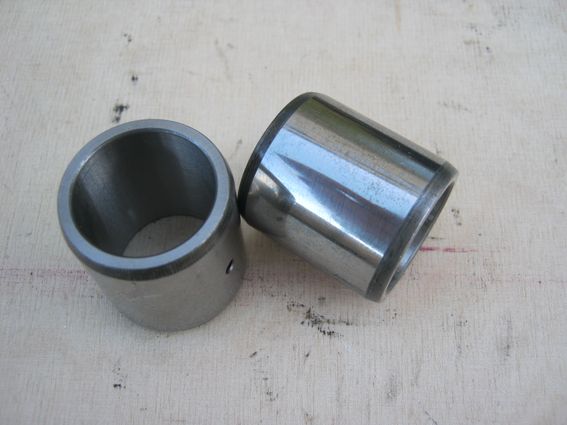
The weights of the standard spacers are as follows:
Front: 143.12g
Rear: 123.68g
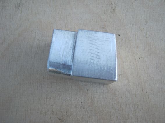
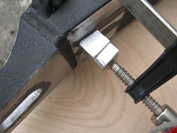
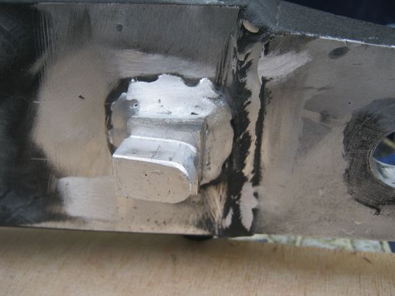
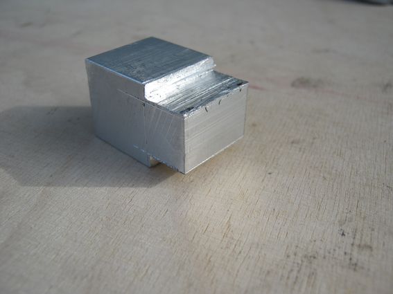
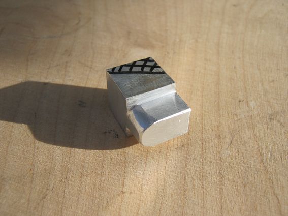
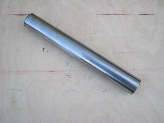
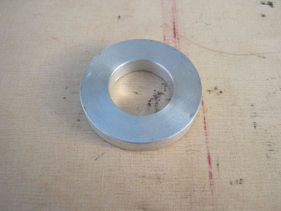
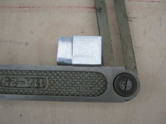
Now i have turned two bits of aluminium down the correct sizes and i just need to drill the 17mm hole through the middle.
I weighed the new bits as they are and measured their dimensions accurately and worked out the density of the aluminium as: 2757.86 kg/m^3
Now when you plug this new density into the required volume of the new spacers you get:
Front: 52.8g
Rear: 45.4g
So a grand weight saving total of (drum roll please)
((143.12+123.68 ) - (52.8+45.4)) = 168.6g
Maccas
-
- Heavy Smoker
- Posts: 476
- Joined: Fri Jun 26, 2009 12:09 am
- Location: Kingdom of the Netherlands
Re: Hybrid project
I don't know enough about carbon fibre to judge whether it would be suitable for spacers etc, especially CF tube under compression. Weightwise it would of course be great! I selected titanium for the swingarm bearing spacer because of its known properties; aluminium woud have been lighter and cheaper but I wasn't quite happy about using a fairly thinwalled part made of that material.
"Mine is a long and sad tale", said the mouse.
"Indeed it is", said Alice, looking at the mouse's tail.
-
- Heavy Smoker
- Posts: 476
- Joined: Fri Jun 26, 2009 12:09 am
- Location: Kingdom of the Netherlands
Re: Hybrid project
The horizontally scribed lines locate the lug vertically:
The RH edge has been given the correct angle (more or less), now for a test fitting:
A strip of brass sheet is used to set side clearance:
More needs to be removed from the lug:
After several bouts of filing and fitting it's off to the welder's:
The RH edge has been given the correct angle (more or less), now for a test fitting:
A strip of brass sheet is used to set side clearance:
More needs to be removed from the lug:
After several bouts of filing and fitting it's off to the welder's:
"Mine is a long and sad tale", said the mouse.
"Indeed it is", said Alice, looking at the mouse's tail.
-
- Heavy Smoker
- Posts: 476
- Joined: Fri Jun 26, 2009 12:09 am
- Location: Kingdom of the Netherlands
Re: Hybrid project
Two days later the welding's done:
Test assembly to see whether it all fits, and it does!
Closeup:
Test assembly to see whether it all fits, and it does!
Closeup:
"Mine is a long and sad tale", said the mouse.
"Indeed it is", said Alice, looking at the mouse's tail.
-
- Heavy Smoker
- Posts: 407
- Joined: Sat Jun 27, 2015 10:51 am
Re: Hybrid project
Quality workmanship as always mate, keep the updates coming...
-
- Heavy Smoker
- Posts: 476
- Joined: Fri Jun 26, 2009 12:09 am
- Location: Kingdom of the Netherlands
Re: Hybrid project
Some time ago KR-1R suggested replacing the standard KIPS servo with a ZXR600's EXUP servo: viewtopic.php?f=8&t=6475&hilit=servo+motor
An EXUP servo was obtained; top is the KR servo, below the ZXR part:
The EXUP mounting bracket was modified, photo shows partly modified state with the second stud bolt still to be removed:
The location for the EXUP servo is determined on the RH frame spar:
Two supporting pillars for the EXUP servo were made, 18 mm OD, 5 mm ID, length 33 mm and tapped for M6 thread. They were then bolted to the modified bracket and clamped down in the desired positions:
Next stop: the welder's shop!
"Mine is a long and sad tale", said the mouse.
"Indeed it is", said Alice, looking at the mouse's tail.