Re: Alternate ign curves
Posted: Fri Sep 16, 2016 5:56 pm
Hello -
I`m Rick, a new member on here and I am also looking for information on aftermarket ignition system setup if anyone can help.
I have spent the last twenty-odd years playing with, and supplying upgrades and tuning parts for, h***a VFRs but recently I`ve been getting the two stroke itch again, so I bought an `89 KR-1 to play with. The bike is all there but in need of some TLC so that`s my project for this winter.
My KR`s ignition system was looking a bit iffy so I have bought an Ignitech system to replace it. I have supplied literally hundreds of those systems for CBRs, RVFs and VFRs and they have proved pretty much bulletproof so a DCCDIP2 unit (same as I use on RC30s) was the obvious choice.
Ignitech supply the DCCDIP2 with the correct configuration and connectors for the KR-1 so it is essentially a `plug and play` unit but their mapping can best be described as `harmless generic` and is a long way from what`s actually required.
Initially I want to set this CDI up as a clone of the stock system so that I have a baseline to work from - I know what the KR-1 advance map looks like but there are a couple of other things that would save me time it takes to figure them out empirically if anyone has the information to hand.
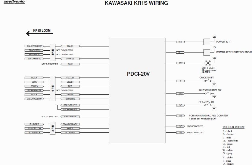
The first one is just a double check to be sure that I haven`t misinterpreted the Zeeltronic charts posted earlier in this thread and concerns the static (mechanical) advance figure for the KR-1/1S motors. I`m taking it that Zeeltronic`s `Static Angle` equates to Ignitech`s `Base Advance`figure, i.e. how many degrees before TDC the pip on the rotor physically triggers the ignition pickup, and that figure is 40 degrees - is that correct? (I know I can check it with a DTI and I will in due course but for the moment I just need to know what that figure should be).
(edit 19/9) OK, a quick try out shows it`s pretty obviously not 40deg static advance, so what is the correct figure (and what is that Static Angle figure on the Zeel?)
Secondly (and my 4-stroke experience is of no help to me here) does anyone have the correct figures for the servomotor output? As I understand it, KIPS is essentially a two position `on-off` system with a transition point at around 8,000rpm - so far so easy but what voltage and `servo hysteresis` figures do I need to make it operate correctly...?
Any assistance will be gratefully received...!
Thanks,
Rick
